Clap circuit switch its diagram working Make a simple electronic clap switch circuit Clap switch circuit using ic 555 timer & without timer block diagram of clap switch
Clap Switch Circuit Diagram Subwoofer Amplifier, Block Diagram, Circuit
Clap circuit switch diagram circuitdigest electronic arduino power sound sensor project circuits block condenser gif board amplifier 555 using ic Switch circuit diagram : simple relay switch circuit diagram Hobby electronic circuits: electronic clap switch
How to make simple clap switch automation
Clap switch circuit using ic 4017Clap switching Switch clap circuit electronic simple make diagram circuits two projects board sound description choose activated electronics homemadeClap switching system based fan block diagram.
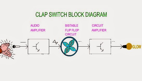
Image result for block diagram for clap switchClap switch electronic project Simple clap switch circuit using 555 timerClap based fan switching system.

Clap block switching system fan diagram based
Clap switchClap on-off switch with 4017 ic & bc547 transistor Clap on clap off switch circuit diagram using 555 timer icSwitch clap circuit diagram projects electronics electronic mini choose board.
Clap switch : circuit diagram, working and its applicationsBuilding a clap switch circuit: a step-by-step guide Clap bc547 transistor circuits cd4017Switch circuit clap diagram working its.

Clap switch circuit diagram using ic 555
Clap switch off circuit diagram 555 using ic timer electronics circuitdigest projects automation sound electronic circuits mic condenser switching dc19 unique block diagram of clap switch Clap circuit 4017 cd4017 mic condenserClap switch circuit diagram subwoofer amplifier, block diagram, circuit.
Relay clap theorycircuit transistorClap switch circuit diagram using ic 555 timer. algebra formulas Electrical & electronics engineering projecct: clap switch making diagramClap switch.

Clap based fan switching system
Clap switch off circuit diagram 74ls74 using project simpleSwitch clap block diagram automation google saved Clap switch electronic education circuitClap switch diagram block switching fig ijser paper.
Clap switch circuit diagram.Clap switch circuit using ic 555 Clap switch : circuit, working, advantages & its disadvantagesEducation of electronic: clap switch.

Mytechpost: our first year project: clap switch
Switch clap diagram block project our transistor year first relayClap 220v lamp 9 way clap switch circuitClap switch circuit diagram using ic 555.
Clap circuit switch diagram electronic power sound sensor circuits led project block condenser gif board 9v arduino circuitdigest 555 usingClap switch circuit diagram project Clap switch circuit diagram transistor relay projectsSwitch clap circuit diagram electronics gif fan transistor making projecct electrical engineering light.

Clap switch : circuit diagram, working and its applications
Diy kit clap switch sound sensor electronic production with e27 bulbClap switch project circuit 555 timer using electronic diagram ic audio sound schematic off electronics led based components without projects Clap switch circuit diagram using 555 and 74ls74Switch clap.
Clap switch circuit simple electronic circuits using cd4017 ic make relay provided readers keen above meClap switch circuit .